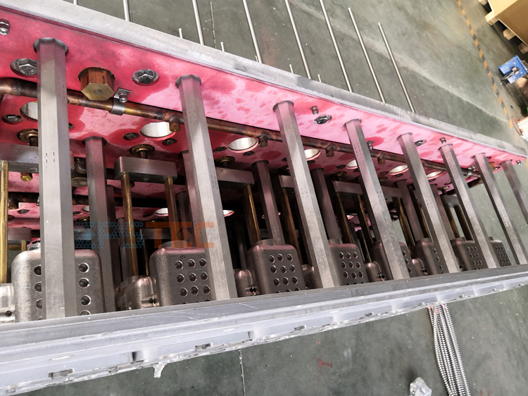


ICF block mold drawing
An ICF mold drawing is a technical blueprint for constructing Insulated Concrete Forms (ICF). It includes dimensions, insulation material, concrete core, reinforcement details, connection features, cutouts, and installation notes. These drawings are crucial for precise and efficient construction.
Suit for EPS machine
Description
An “ICF mold drawing” refers to a technical drawing or blueprint for an Insulated Concrete Form (ICF) mold. Insulated Concrete Forms are a modern construction method where reinforced concrete is poured into a mold made of foam insulation. This method is used to create energy-efficient and sturdy buildings.
Here’s a breakdown of what an ICF mold drawing typically includes:
- Dimensions and Design: The drawing will show the dimensions of the ICF blocks or panels, including length, width, and height. It may also detail the interlocking design, if applicable.
- Insulation Material: It specifies the type of foam insulation used (e.g., expanded polystyrene (EPS), extruded polystyrene (XPS)) and its thickness.
- Concrete Core: The drawing will indicate the size and shape of the space where concrete is to be poured, known as the concrete core.
- Reinforcement Details: It may include details about the placement of steel reinforcements (rebar) within the concrete core.
- Connection and Alignment Features: The drawing will show how individual ICF units connect and align with each other, which is crucial for the structural integrity of the building.
- Cutouts and Openings: Details of any cutouts for doors, windows, and other openings will be included.
- Installation Notes: There might be notes on the installation process, handling of the ICFs, and any special considerations for the construction.
ICF mold drawings are essential in the planning and construction phases, ensuring that the ICF blocks or panels are manufactured to precise specifications for efficient and effective building construction.
Photo
55mm


105mm


Leave a Message